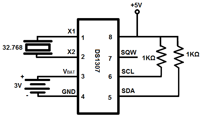
Ds1307 circuit real time clock rtc vdd interfacing schematic diagram 5v pins supplied must How to use a real time clock module with the arduino circuit basics Esp32 ds3231 clock module real time diagram circuit using display rtc oled circuitdigest esp connect esp8266 given below board article
Real Time Clock with Alarm Option using AT89S52 and DS1307 IC
Clock real time circuit seekic diagram control Clock circuit alarm ds1307 microcontroller engineersgarage proteus arduino lcd rtc Real time clock circuit diagram ds1307
Real time digital clock circuit diagram
Clock circuit ds1307 real time 16f88 segment circuits rtc seven only diagram microcontroller electronic projects using sameArduino clock time real ds1307 rtc module using circuit diagram interfacing Clock real time avr diagram using blockHow to build a real-time clock circuit with a ds1307 chip.
Clock time real engineersgarage saved circuit diagramAt89c4051 digital real time clock circuit Real time clock with pic16f877a, ssd1306 oled and ds1307Real time clock.

At89c4051 digital real time clock circuit under repository-circuits
Pcf8583 real time seven segment clock circuitDs1202 real-time clock Ds1307 clock time real schematic module i2c rtc electronics lab acoptexAlarm clock circuit diagram.
Ds1307 rtc moduleRtc module ds3231 clock real time arduino Circuit ds1307 clock time real rtc fig electro microcontroller interfaceDs1302 clock time real circuit lcd 16f88 microcontroller schematic projects circuits.

Real time clock ds1307 interfacing with arduino
How to build a real-time clock circuit with an arduinoCircuit diagram of real time clock Digital clock circuit using ic 555 and ic 4026 – diy electronics projectsClock digital circuit ic using 555 diy diagram segment display project electronics arduino board projects ics hub above resolution high.
Arduino real time clock using ds1307 rtc moduleClock circuit digital diagram arduino real time atmega328p using micro make pu Interfacing pic16f84a with ds1307 real time clockCircuit ds3231 clock real time ccs.

Clock circuit digital real time rtc diagram seekic popular using schematic lcd gr next figure circuits
Real time clock seekic circuit diagram controlDs1302 real time lcd clock circuit Make real time digital clock using atmega328p-pu micro controller orDs1307 real time clock module.
Real time clock(how to interface ds1307 rtc to at89s52 microcontroller)Real-time clock circuit using mcu pic16f84a Real time clock with alarm option using at89s52 and ds1307 icHow to use a real-time clock module with the arduino.

Clock real time circuit arduino rtc build
Real time clock circuit diagramReal time clock circuit diagram Real time clock and calendar using ds3231 and pic16f877aArduino rtc ds3231 iic memory circuitbasics.
Ds1307 clock time real circuit diagram arduino interfacingReal time digital clock circuit diagram Real time digital clock circuit diagramCircuit clock real time ds1307 rtc breadboard schematic build chip oscillator crystal.

Oled ssd1306 circuit ds1307 clock real time diagram display grounded connected terminals together
World of embedded: real time clock using avrClock circuit Esp32 real time clock using ds3231 module and oled displayLoadedcircuit.com: real-time clock with remote-controlled.
How to interface ds3231 real time clock with arduino rtc module withDs3231 real time clock module rtc Clock module ds1307 rtc arduino circuit.


DS1202 Real-time Clock - Control_Circuit - Circuit Diagram - SeekIC.com

Real Time Digital Clock Circuit Diagram

How to Use a Real-time Clock Module with the Arduino - Circuit Basics

Real Time Clock with Alarm Option using AT89S52 and DS1307 IC

real time clock DS1307 interfacing with Arduino

Real Time Clock Circuit Diagram
